
MegaBACE resource page
Multi capillary electrophoresis instrument with laser induced fluorescence
This page will contain a collection of useful information about the capillary electrophoresis instrument MegaBACE. The lab got its first instrument in January 2001 and the instrument is still in working condition. Although an old instrument it is still very usefull as a tool for separating DNA. However, the instrument support was terminated by GE healthcare more than 10 years ago. More "historical" background can be found at the following webpages.
One problem with old instruments is to obtain spare parts. Thus, webpages like Ebay or LabX becoms very useful. In addition there are many companies that sell secondhand instruments which can be used as a parts resource.
The MegaBACE instrument came in three different configurations. With either 48, 96 or 384 capillaries. The latter only had one blue (488nm) laser while the versions with fewer capillaries had blue and green (532nm) laser. The laser energy was transfers to the capillaries by confocal scanning (as shown).
The light path of the two lasers are combined by a series of mirrors and beam splitters, while the fluorescent signal is reflected to the photo multiplier tubes by the moving beam reflector (in the back) seen to the right. The scanning stages focus the laser beam with an objective onto the capillary windows. For the instrument to operate properly it is vital the lasers are aligned correctly. This was usually done once a year by a service technician. So when the instrument support was discontinued users had to perform the laser alignment.
The schematics of the light path.
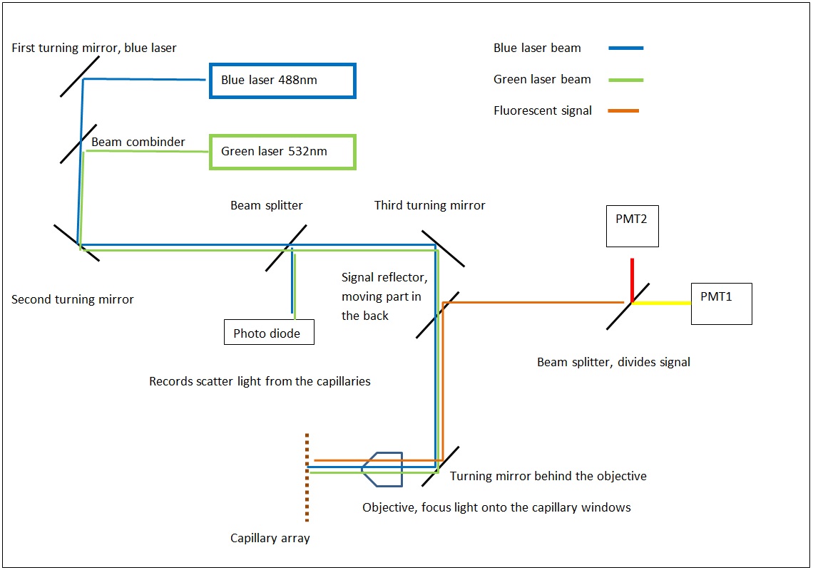
click to enlarge
MegaBACE Service Manual, Revision 2 March 2001
MegaBACE 1000 DNA Analysis System May 2003 (parts list). For information only.
Laser aligment
The lasers are aligned by use of pinhole targets so the light paths are center in X Y Z axes. Unfortunately no user manuals have any detailed description of the procedure. As a second best some written note for a Danish service person is available but it is written in Danish (link to alignment notes). A direct google translated version to English can be viewed here.
The picture below show a top view of a MegaBACE 1000 without covers.
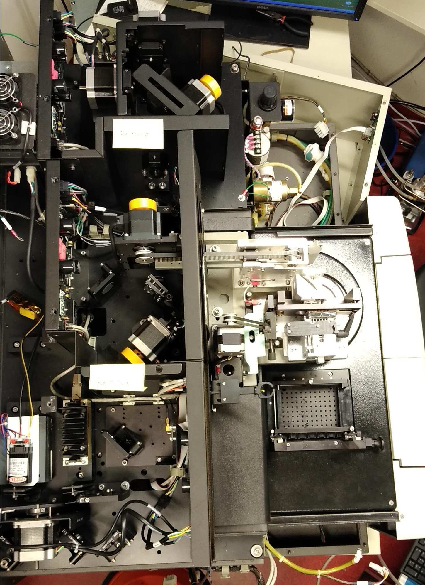
Click to enlarge
Running buffer
The standard electrophoresis protocol in the MegaBACE1000 was to run with 1Xbuffer on the cathode side while the capillaries were submerged in the polymer tube on the anode side. And after the "run" the polymer tube was discarded. To reduce the polymer consumption, a simple trick of replacing polymer tubes on the anode side with 1x buffer tube after replacement of polymer and before the electrophoresis would reduce the running cost ten-fold. The polymer tubes could be used for more than 10 polymer replacements, as long as they were kept at +4°C when not in use.
MegaBACE 1000 10Xbuffer
Containing
300 mM Trizma®Base,
1M TAPS,10 mM
0.5MEDTA, pH adjusted to 8.5
To make one liter 10Xrunning buffer, take 243.3 g TAPS, 36.36g Trizma® base and 20ml 0.5M solution EDTA and reconstitute to 1 liter with H2O. Adjust pH to 8.1 with 5M NaOH (CAUTION). Sterile filter the solution and store 4°C. The 1x running buffer is made by taking 100ml 10xbuffer and diluting it with 900ml H2O. The 1x buffer can be stored at room temperature.
Trizma® base
2-Amino-2-(hydroxymethyl)-1,3-propanediol, THAM, Tris base, Tris(hydroxymethyl)aminomethane, Trometamol
Linear Formula:NH2C(CH2OH)3
Molecular Weight:121.14
TAPS
N-[Tris(hydroxymethyl)methyl]-3-aminopropanesulfonic acid, [(2-Hydroxy-1,1-bis(hydroxymethyl)ethyl)amino]-1-propanesulfonic acid
Linear Formula:C7H17NO6S
Molecular Weight:243.28
EDTA
Ethylenediaminetetraacetic acid
Linear Formula:(HO2CCH2)2NCH2CH2N(CH2CO2H)2
Molecular Weight:292.24
Capillary array
The capillary arrays is assembled as sets 16 or 64 capillaries for used in the 96 or 384 systems, respectively. The polymer used to separate DNA is a 3% linear polyacrylamide in 1X running buffer and 6M urea. Since this polymer does not have dynamic coating properties the internal wall of the capillaries need to be coated to suppress electro-osmotic flow. The life time of the coating was in the past guaranteed to be stable for 200-250 runs. At which point the arrays needed to be replaced. However, by reducing the polymer injection time from 200 second to 40 second the capillary coating would last for ~1000 runs. Signs of insufficient coating would be unstable current and decreased peak resolution.
Re-coating of capillaries
Capillaries that show sign of deteriorated coating can be re-coated by a modified protocol based on the work of Stellan Hjertén.
The residual polymer inside the capillaries is removed by the flush and dry protocol. This is a series of flushing the capillaries with H2O. Flush the capillaries with water at least 7 times. This is followed by a single flush with 100% acetic acid (if Instrument Control Studio (ICS), use the command Hipress 7). Now a mix of 1ml 100% acetic acid, 1ml M6514 (3-(Trimethoxysilyl)propyl methacrylate) (Sigma-Aldrich) and 14 ml H20 is injected into the capillaries by use of hi pressure (Hipress 8) and should sit for at least 2 hours or over night. This should result in a covalent bond silane groups to inner wall, upon where acryalimde chains can be built in the next step.
Next a mixture of 12ml 1x MegaBACE running buffer, 300 microliter 40% acrylamide monomers and 6 µl TEMED (N,N,N′,N′-Tetramethylethylenediamine) is prepared and injected into the capillaries. This is followed by an electrophoresis step where ammonium persulfate (APS) (a radical initiators of the polymerization) is introduced into the capillaries. Thus, prepare a solution with 2250 µl 1x MegaBACE running buffer with 250 µl APS 20% and dispense into a 96 well plate. This plate should be put on the cathode side of the capillaries. Run electrophoresis at 3000 volt with blue and green laser. The initiator should now migrate into the capillaries and starts the polymerization on the inside of the capillary walls.
Polymer
The separation matrix used for the MegaBACE is still available from the Gel Company. However, to reduce cost one might consider making in lab formulation of linear polyacrylamide. The formulation needs to be kept at +4°C because of degradation of urea. A general recipe would involve the following steps: Add 1x MegaBACE running buffer appropriate flask/beaker, add 6M urea, 3% acrylamide monomers, degas (remove ALL oxygen). Purge with argon gas, or sonicate under vacuum. Start reaction with 125 microliter 20% APS (fresh) (ammonium persulfate) 25 microliter 100% TEMED. Stir slowly without oxygen present, as this (oxygen) will terminate the polymerization.
While the polymer cures drink some wine, could take days.
MegaBACE waste/water tank
A spare tank can be 3D printed. File is uploaded here.
Blue laser alternative
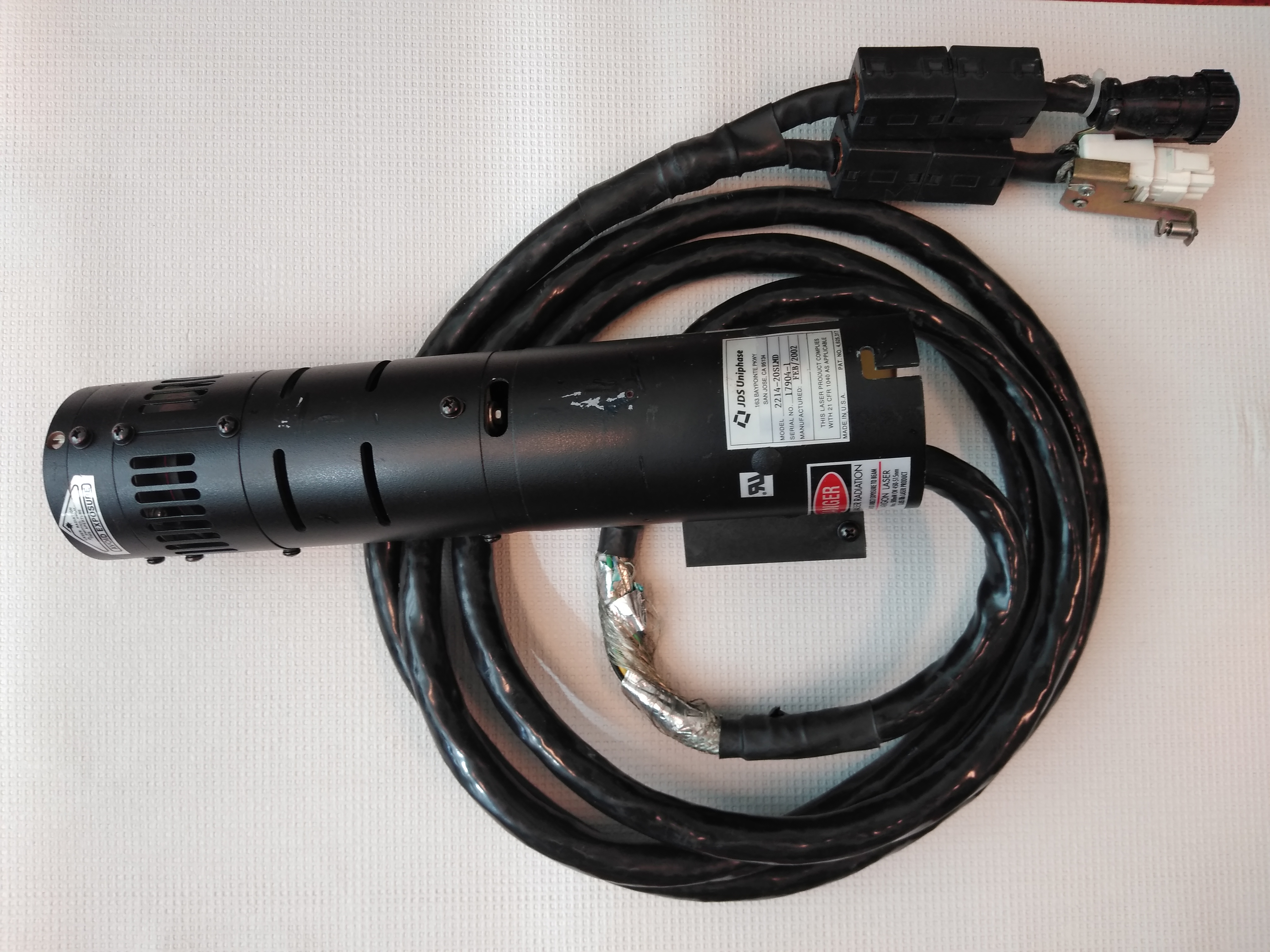 The original blue (488nm) laser is an argon gas laser from JDS Uniphase (2214-20SLMD). It has a high power consumption and produces a lot of heat that is extracted by the big fan module. To be able to replace this laser with a modern blue (488nm) solid-state laser the MegaBACE need to "believe" that the argon laser is still running. There is a feedback loop through the DB25 cable going from the MegaBACE to the laser power supply. To trick the MegaBACE a few jumpers are needed as well as a low amp (<20mA) 10 to15V DC power source (5X3V Cr2032 batteries will do the trick). The DB25 cable needs a jumper between 1 and 3, 7 and 8, 8 and 9 and the +10V DC on 13 and -10V DC on 14. There is also a switch the registers the airflow over the argon laser. This switch is located in the back of the upper right-hand side in the round airflow channel. The switch needs to be connected. Now the MegaBACE can run with a separate solid-state laser instead of the argon laser.
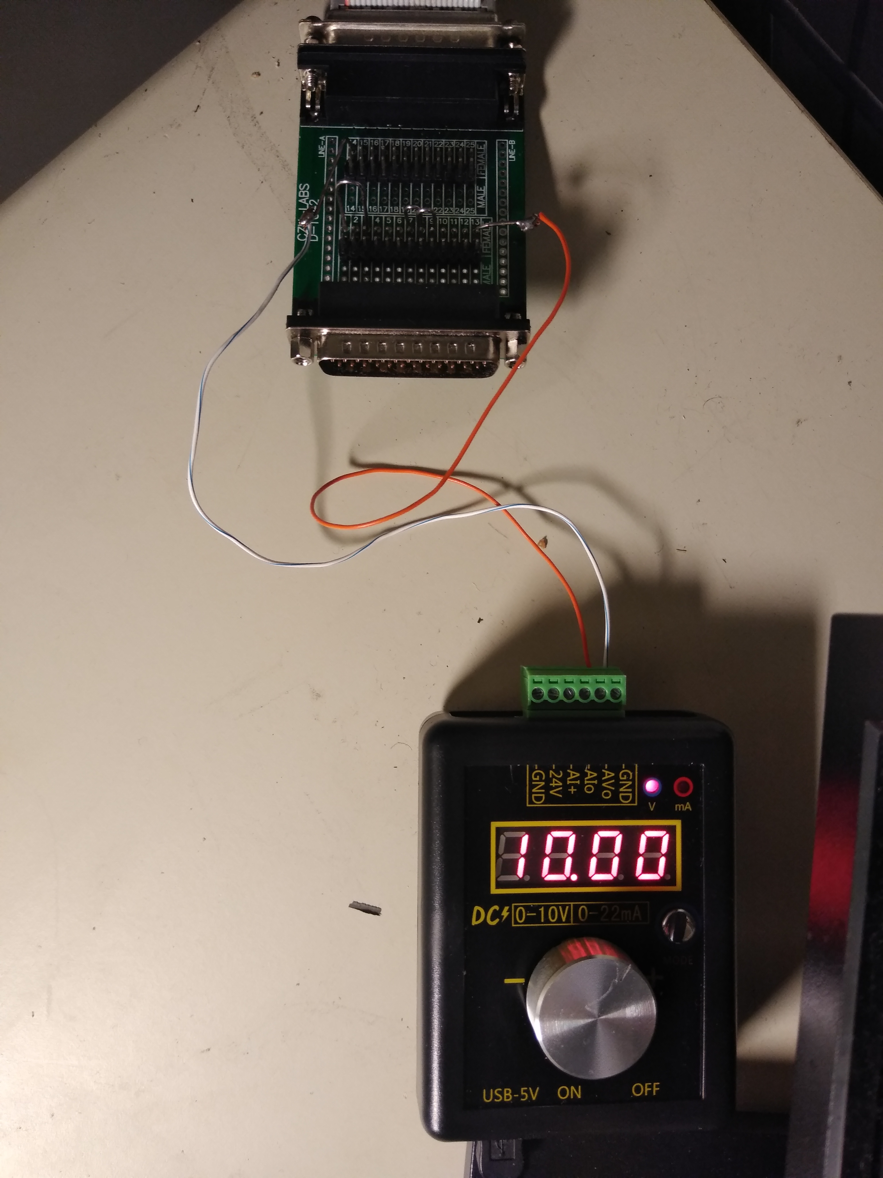 The setup in the picture on the right is one way to supply the signal to the DB25 cable. The voltage is set to 10V with 10mA and jumpers on the connection board. A comparison of the signal with the original and alternative laser is shown here for the same sample.
Temperature failure
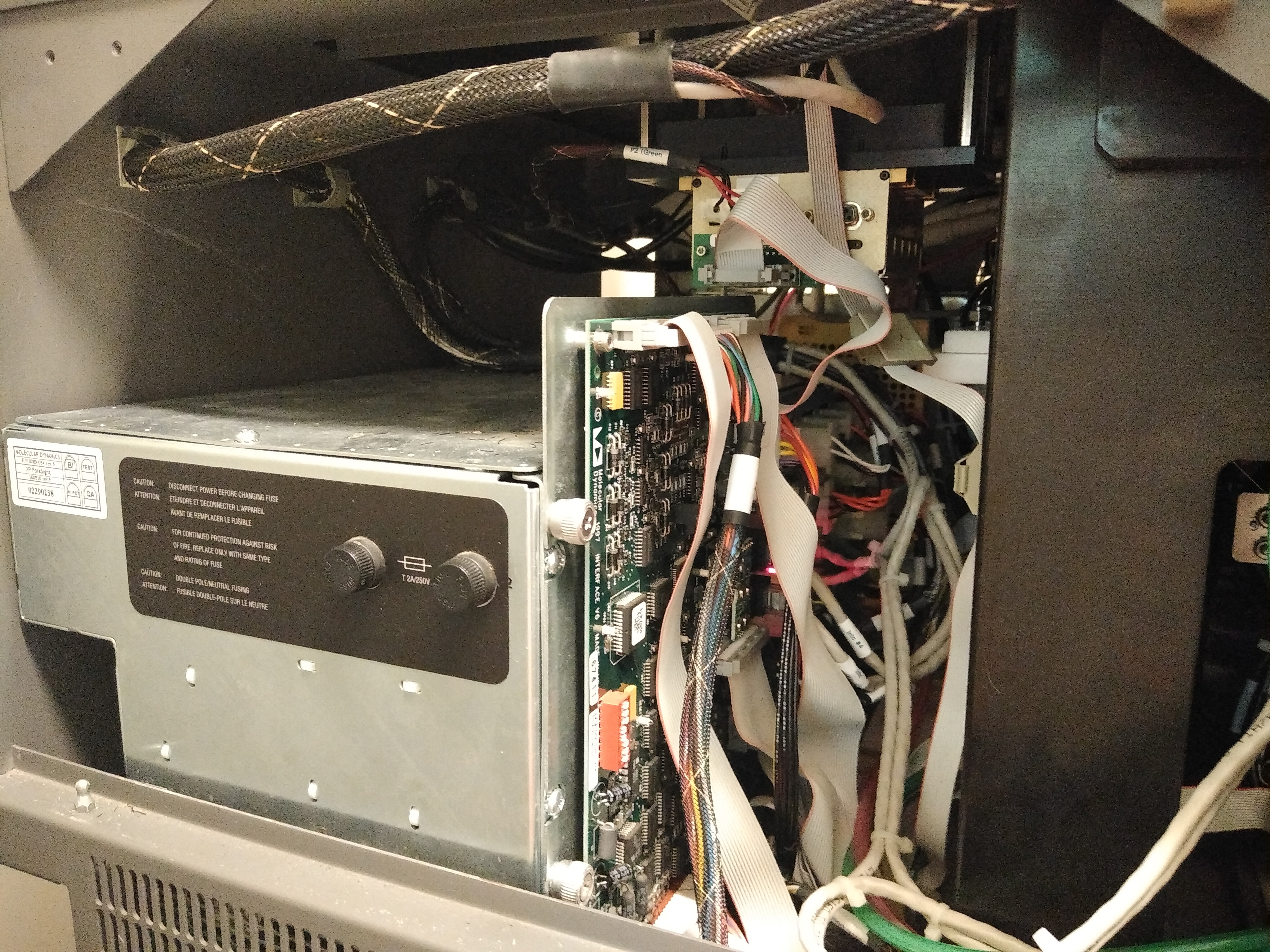
We have experienced a failure of the oven on the MegaBACE. Every time the problem was caused by a faulty bridge rectifier. This is part that costs 2-3$ and can be replaced with a bit of work. To access the power supply, remove the left side panel of the instrument. Resting on the bottom of the MegaBACE and towards the back is a big power supply.
Power supply
Click to enlarge
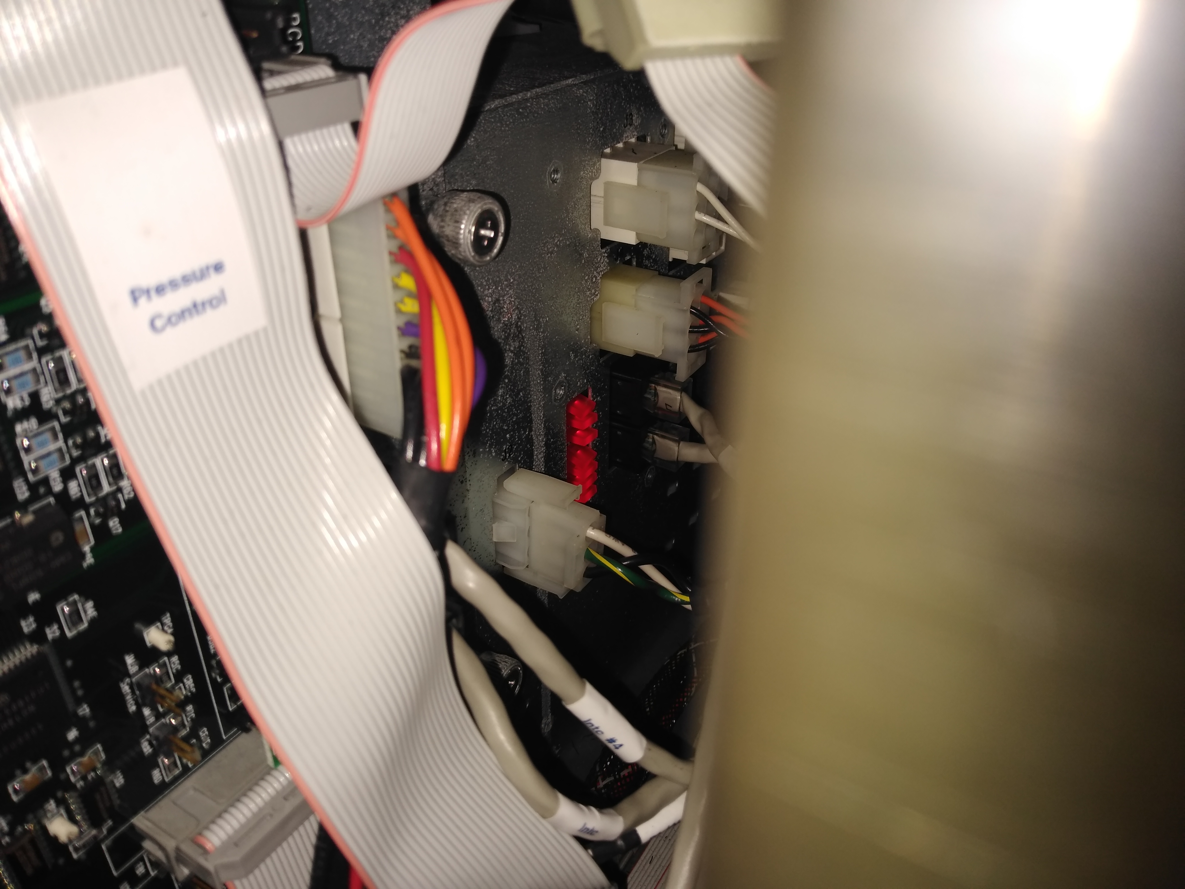
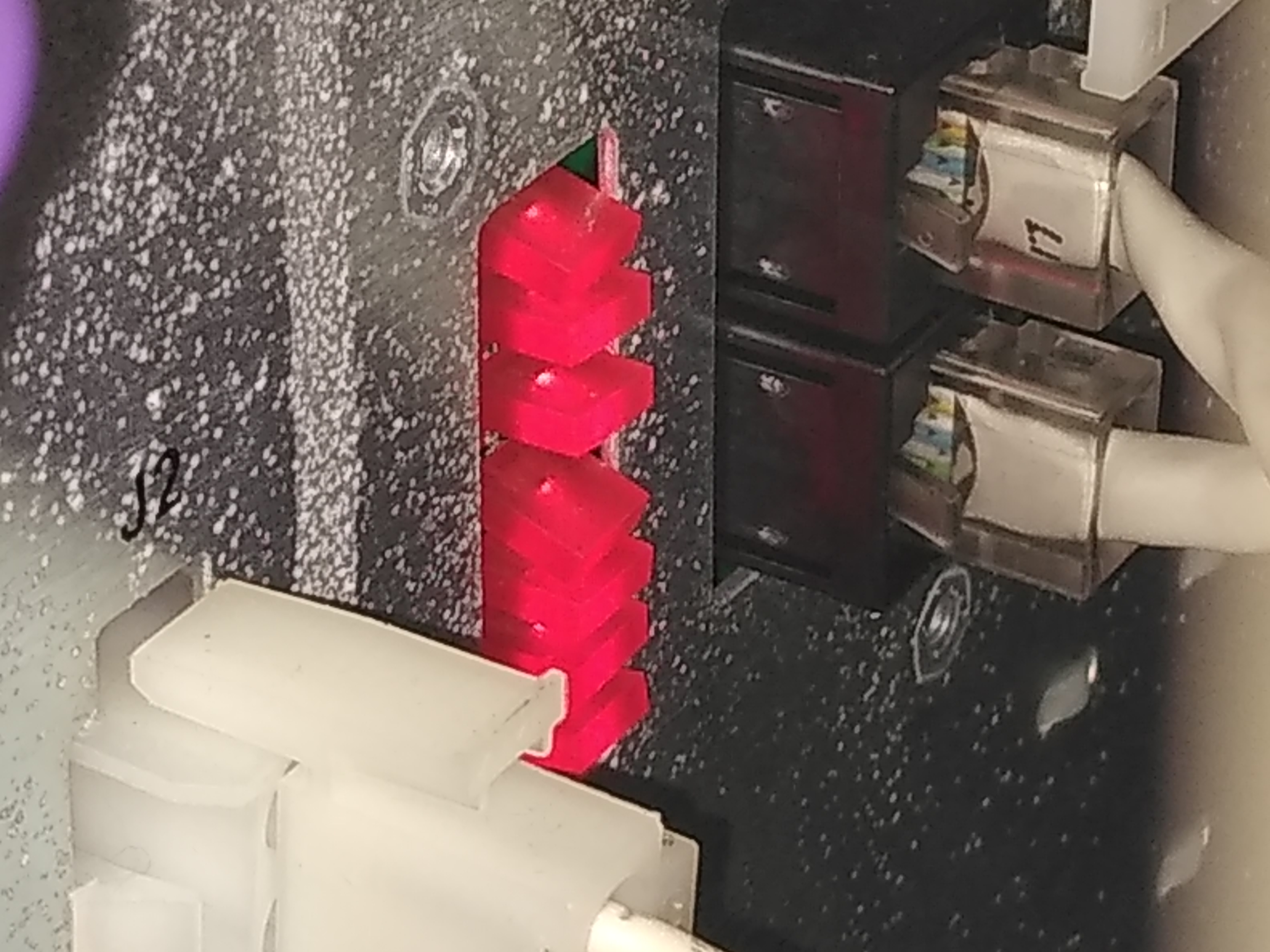
On the power supply, 7 red diodes should glow when all the circuits in the power supply are in order. If one is not glowing then that is a good indication that the bridge rectifier needs to be replaced.
Diodes in the back Diodes
Click to enlarge
Now, the power supply has to be taken out of the MegaBACE. Turn off the instrument and label all the cables. Disconnect all the cables attached to the power supply. The connections on the "computer card" do not need to be taken out, because the card is a separate unit that rests on the power supply. It has to be detached by loosening four Philips screw bolts. There is one connection on the right-hand side of the power supply; this can be accessed by the little porthole on the back of the instrument. Finally, remove the screws on the back of the instrument that fix the power supply to the MegaBACE. The screws go through the cabinet and into the power supply. Now gently wiggle and lift the power supply out on the left side on the instrument.
When the power supply is removed from the instrument, remove the top lid and look for a part as shown below. It should be located in the bottom underneath/next big "big" blue capacitor. BE CAREFUL capacitors can hold a large amount of charge even if the power supply is not connected to any power source. It is possible to loosen the front panel to get better access to the rectifier. But beware of all the connections on the front panel.
Bridge rectifier

Temperature limitation
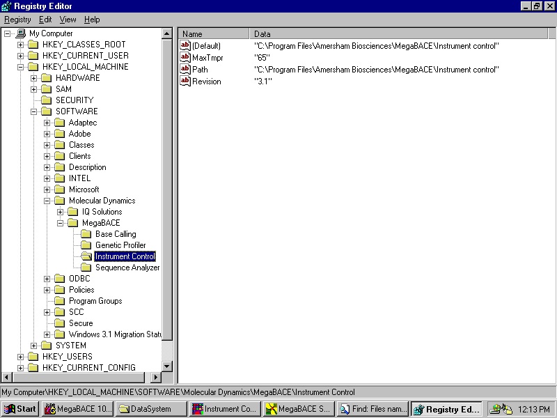
A standard instrument has a limitation on the temperature. This can be changed by replacing "tmpr.nxe" file with a newer version and changing the limitation in the registry. The life opens in a new window in the web browser. Save the file as text and rename the file "tmpr.nxe".
- Back door for changing the upper limit for the temperature in the ICM.
9.1 If the string value (case sensitive):
HKEY_LOCAL_MACHINE\SOFTWARE\Molecular Dynamics\
MegaBACE\Instrument Control\MaxTmpr
Exists in the Registry and its data specifies a valid number larger than the lower limit for the temperature in the ICM (currently 27°C), then on start up the ICM will substitute the internal (hardcoded) upper limit (currently 44°C) with this value. This feature is for in-house use only, the Registry value will not be supplied by the installer.
Software
The MegaBACE software originally ran on Windows NT (that's a long time ago). Instrument control manager (ICM) is the software used to control the MegaBACE through predetermined "scripts". To alter or modify the scripts a "text" file called "macro.ini" needs to be opened and changed before starting ICM. Instrument Control Studio is software that allows for more manual operation of the MegaBACE. The view and edit software can display the electropherogram and export data to text file. Since the base caller is a licensed product, it is not part of this software. As a precaution for computer crashes and loss of vital software, there are copies stored in a google drive.
The following link can be used to obtain copies of the useful MegaBACE software.
Instrument control studio: ICS
Instrument control manager: ICM 3.1
Display electropherograms: View and edit
PDF documentation
 User manuals in different versions are available as PDF file.
MegaBACE 4500 Version 4.0 User’s Guide Addendum
MegaBACE 500 and 1000 Version 3.1 New Features Guide
MegaBACE Version 2.4 Instrument Administrator’s Guide
MegaBACE Version 2.4 Maintenance and Troubleshooting Guide
MegaBACE Version 2.4 Operator’s Guide
MegaBACE Version 2.5 SNP Genotyping Administrator’s Guide
MegaBACE Version 2.5 SNP Genotyping Operator’s Guide
MegaBACE Chapter 6 Instrumentation and detection (good description of mirrors and optic)
MegaBACE Planning guide
Contact info
For questions or if you want to contribute with additional information please feel free to send an e-mail to pok[.at.]ous-hf.no